Project ToyoRati: FR-S with a Maserati V8...

56
United States
United States
I'm currently in the early build and planning stages of the project.

The What :. SCCA Time Trials Max category is a pretty much open ruleset, save a few small pieces, factory car wheelbase, engines must remain in the same origination, no tube frames.

I'm working to build a Scion FRS for this category, in the Max 3 ruleset. What that means, 2500lbs or 95% of factory weight with driver. NA factory engines under 4.5l or Factory turbo engines under 2.9l.

I'm going to be using a Maserati F136s, 4.2l and 395hp with dry sump oiling from the factory.

The Why : a certain group of competitors think the Cayman GT4 cannot be beat in that class. My goal is to prove them wrong. By a lot.

The When : TTNats 2023, October 12th, to be specific

The How : a lot of sleepless nights, bounced checks, blood, sweat, and a lot of tears.

I'm chronicling the process on YouTube, because why not?

https://youtube.com/playlist?list=PLkZmuSgYhxRaghZ5__At7TZX7iZuC45Rsht tps://youtube.com/playlist?list=PLkZmuSgYhxRaghZ5__At7TZX7iZuC45Rs

Lemme know what you guys think!
 
Maserati engine in a Scion/Toyota/Subaru?

Tell Schitts Creek GIF by CBC
 
Yup, its insane, dumb, over-ambitious, and I hope it is as awesome as I am dreaming it to be.

The majority of my updates will be in that playlist.

Feel free to ask any questions and I will try to answer any questions in a timely fashion.
 
Just an update since I haven't had a video in a while.

I am still waiting for some odds and ends to be delivered.

I designed a bronze bushing for the shift housing that has o-rings in it, once the bushing shows up I can finalize the housing for the shifter and get it made and move onto the cable linkage next.

I'm also waiting on a few more parts to be 3D printed for the torque tube. I have the basic design for the transmission side of the driveshaft to transmission input shaft made up and a friend is printing it. Once that is done, I can test assemble all of the components for the torque tube on the transmission side. I'm having to make a slight redesign of the clutch side of the torque tube flange to allow the higher engine speed of the F136 to not nuke the bearing that works for the Corvette. I hope to have that figured out and finalized pretty quick.

Once that is all done, I will be able to start the process of mounting the engine and transmission!
 
Weekly update, because I don't have a video to post today.


Ok, I just placed the order for my shift selector housing assembly. I made some minor changes to the plans on the design. I ended up having the threads cut into the design so I didn't have to deal with the effort, and possibly breaking a tap inside of a something so important.


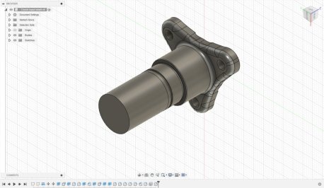
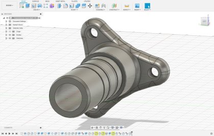
1st photo is the topside view

2nd is the housing I have designed in relation to the Ferrari/Maserati actuator

3rd is Underside of my design

ETA on this part is 3 weeks.


I have the input shafts for the propeller shaft of the torque tube drawn up and pretty much finalized. My next step on this is to get that put into an engineering drawing and the machine shop will get that part rolling, add that to another thing I have never done before and need to learn. the material will be in 8620 and then heat treated. roughly 8-10 weeks out on this at the earliest.

Clutch input shaft is the 4th picture
1000001557.jpg
Transmission input shaft is the 5th picture
1000001556.jpg

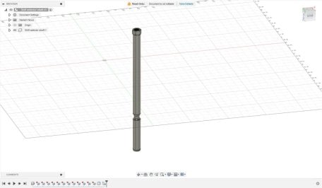
The Shifter selector rod is currently with the machine shop and should be getting cut within the next few days. Once I have that done, I will run it over to a plating company and have it coated with electroless nickle to allow it a super smooth and low resistance finish. Just like the manually shifted and controlled Ferrari/Maserati cars. I might have it done within the next 2-3 weeks.


The shifter rod is photo number 6
1000001558.jpg


I just want to add, the propeller shaft design is a direct copy from a C6 corvette, that will have the splines from the Maserati requirements cut into them.
 
Last edited:
Just a little bit of an update while I wait for parts to show up...I know, I say it everytime I make a post...

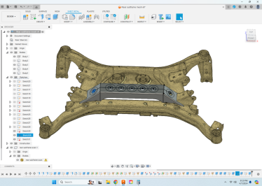
I was able to get a 3D scan from a user on FT Club, and that was a MASSIVE help to make up some things. It allowed me the ability to use the scan data, and essentially form my brace to fit the subframe almost perfectly. Please see below.


I could have just made this from cardboard, and it might have been faster, but the finished product as this sits is repeatable. Which is super important to me in the case of something failing or getting destroyed in a collision, remeber, this is a track car first and foremost.

Let me know what you think.
 

Attachments

  • Subframe brace.png
    Subframe brace.png
    166.4 KB · Views: 8
Just a little bit of an update while I wait for parts to show up...I know, I say it everytime I make a post...

I was able to get a 3D scan from a user on FT Club, and that was a MASSIVE help to make up some things. It allowed me the ability to use the scan data, and essentially form my brace to fit the subframe almost perfectly. Please see below.


I could have just made this from cardboard, and it might have been faster, but the finished product as this sits is repeatable. Which is super important to me in the case of something failing or getting destroyed in a collision, remeber, this is a track car first and foremost.

Let me know what you think.
Properly developed part > one off fabricated piece. I like the way you are approaching this project. I haven't watched any of the videos - what transmission are you going to be using?
 
Properly developed part > one off fabricated piece. I like the way you are approaching this project. I haven't watched any of the videos - what transmission are you going to be using?


I am using the Maserati transaxle, which is a formerly robotized manual transmission. This reinforcement is to strengthen up the area that I have cut out of the factory rear subframe to fit the transaxle. This is purely for weight distribution to help handle the increase in power and torque. Goal power number are around 350whp and 300wtq
 
I finally have an update, but I am having trouble embedding photos into this post. I don't know why.

Please see my instagram post as follows.

 
Last edited:
I am still plugging away with no real news just yet.

Work has been in the way, replacing the cam phasers in my F150, doing a rear suspension overhaul on my buddies cayenne, painting my house....

Now it's time to get hard into the work.

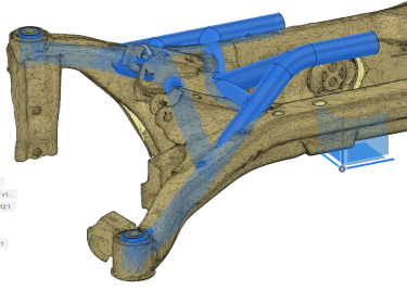
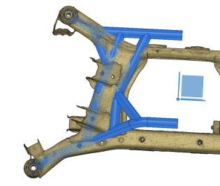
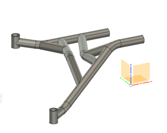
I'm currently working with a 3D scan to create a tubular subframe design. I'm planning on doing the subframe work in Docol R8, 1.5in x 0.095 wall thickness. Should be stronger then the factory frame, and weigh about the same or possibly a touch less.

With the new rules, I'm trying to decide if I want to run in Max 4 at 3000 lbs with driver and whatever power I can get out of the car, or run my originally planned weight of 2700lbs with driver and end up in Max 2

Photos for funsies.

Please help me decide on the Max 4 v Max 2 and give me some critique on the subframe design ...
 

Attachments

  • Screenshot 2024-11-25 204425.png
    Screenshot 2024-11-25 204425.png
    103.5 KB · Views: 1
  • Screenshot 2024-11-25 204531.png
    Screenshot 2024-11-25 204531.png
    98.2 KB · Views: 1
  • Screenshot 2024-11-25 204405.png
    Screenshot 2024-11-25 204405.png
    16.2 KB · Views: 1
Back