T300RS Pedal Wiring Diagram

  • Thread starter camasaki
  • 29 comments
  • 33,957 views
23
Switzerland
Switzerland
Does anyone know how the T300RS expects pedal wires? I have a T100* pedal set and would like to use it with the T300 base - I've modified the plug but it's not recognized. I assume it's just all potentiometers so I just need to cross some wires around.

My T3P wires: White Brown Red Green Yellow Blue
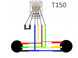
My T100* wires: Blue Yellow Brown Green

Looking inside the T100* yellow is the Acc and Green the Brake (each coming from the middle of the pot). Brown is then the bottom of each pot and blue the top.

* UPDATE: In my original post I mistakenly wrote "T150". What I have is the T100 pedal set.
 
Last edited:
T100 wiring - pots viewed from the bottom (underneath the pot).
 

Attachments

  • s1.png
    s1.png
    5.4 KB · Views: 1,166
Last edited:
I'm sure the pinout is the same for T150 and T300, since e.g. T3PA Pro pedals are tagged as compatible with both.

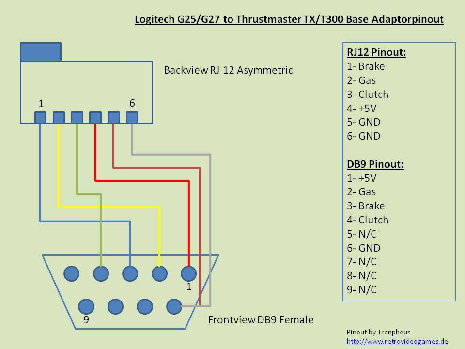
I used this diagram to make an adapter to T300 for Logitech pedals, so can confirm the info is correct:

cache_2456345201.jpg


(from here)
 
My apologies - I meant to write T100 not T150.

The pedals I have (Brake and Acc - no clutch) have a standard RJ12 plug and not the "RJ12/6 plug with offset lug" which fits a T300/T500.
 
Its hard for me to order to thrustmaster the adaptor coz there is no shipping in kuwait. Pls help me
Thank u
 
Last edited:
I'm sure the pinout is the same for T150 and T300, since e.g. T3PA Pro pedals are tagged as compatible with both.

I used this diagram to make an adapter to T300 for Logitech pedals, so can confirm the info is correct:

cache_2456345201.jpg


(from here)

Can you explain where the wires go to on the pedals? Which wires on the actual potentiometers...
 
I also measured the voltage on the T300 and white was +5v - the only wire with a voltage which doesn’t tally with your diagam which says red is positive.
 
Can you explain where the wires go to on the pedals? Which wires on the actual potentiometers...
This is for T150 pedals:

STb12x9.jpg


Throttle:

CoDAFlS.jpg

ECae1QQ.jpg


Brake:

ZvboyOZ.jpg

0xPkdpm.jpg


Keep in mind that I had to swap the wires at both ends of the brake potentiometer because in the original T150 pedals both potentiometers point in one direction while here the brake potentiometer is directed against the throttle potentiometer.
 
Hi is the diagram of t300rs to g29 pedal working 100 percent. Thnx

Yes, all 3 pedals work perfectly with the adapter.

Just one thing - if you have a metal rig and hard-mounting T300 wheel and Logitech pedals to it, you'll have to make sure the bolts do not also make an electrical connection. Easiest solution is to use electrical tape and plastic washers on the bolts for the pedals. This is because the +5V and GND are swapped by the adapter (otherwise the pedals would work backwards).


Can you explain where the wires go to on the pedals? Which wires on the actual potentiometers...

Gas/Brake/Clutch go to the middle pins on each pot.

For the +5V and GND I'm not sure since I've never seen the T100 pedals. I'm guessing, but I think the bottom pins would be +5V and the top ones GND... better shown by @super_gt post above, since it depends on which side of the pedal the pot is mounted.

I also measured the voltage on the T300 and white was +5v - the only wire with a voltage which doesn’t tally with your diagam which says red is positive.

I suspect the white wire might be used to let the wheel know that it has pedals attached but I haven't verified that. I can say for sure that the adapter I built connects pin 6 to pin 5 of the RJ12 without any smoke appearing!

Did the red show +5V?

Might be able to check some more on my wheel over the weekend.
 
Hi, I hope everyone is having an amazing day. I have Logitech G27 Pedals and Thrustmaster T150. I cut the RJ 12 cable from the original T150 Pedals. I want to use the Logitech Pedals with the Thrustmaster wheel. If you please can someone right now tell me which wires should I connect to which. Thank you very much!

If someone could help right now this will be super super amazing! waiting!!!

RJ12 wires: blue, yellow, red, green, brown, white.

Logitech Wires: orange, white, red, black, green.
I'm sorry but I've never had G27 pedals and I can't help you with the wiring, but there is an adapter for that- DB9 PEDALS T.RJ12 ADAPTER
 
I don't know the colours of the G29, sorry. I only made an adapter based on the pinouts.

The diagram in post 4 shows colours for the Thrustmaster side, I think (white = grey).
cache_2456345201.jpg


This shows the Logitech colours (but note this is looking at the other side of the 9-pin connector!):
g25pinout-png.148609


So based on those I think it would be:
TM --- Logi
Blue --- White
Yellow --- Orange
Green --- Green
Red --- Black
Brown & Grey --- Red

Yes, +5V and 0V are supposed to be swapped around like that!

I haven't done this so I don't know if it is correct. USE AT YOUR OWN RISK :)

Also heed the warning near the top of post #11 about using adapted pedals on metal rigs.
 
Last edited:
Thank you so much, it works now. But there is one big problem. The clutch and brake are working perfectly but the throttle isn't recognized at all!!!! @Outspacer

Since everything else is working I'd have to guess at some problem with the Yellow to Orange connection, or a break in one of those wires, or that one of them is shorted to something else.
 
I checked everything from drivers to wiring. Everything is working perfectly except for the throttle!!! This is very strange, it should all work or nothing. If you can help me this will be the most amazing christmas gift ever!!!!
 
I checked everything from drivers to wiring. Everything is working perfectly except for the throttle!!! This is very strange, it should all work or nothing. If you can help me this will be the most amazing christmas gift ever!!!!

Do you have or could you borrow a multimeter? Because after checking the yellow to orange connection is good again, testing the wires would be the next step. I can't really help beyond that except to repeat my last post - it's quite clear there's something wrong with only that yellow-orange connection or wires, not very strange at all!
 
I used a tester and the yellow wire is ok, but the throttle isn't working!!! @Outspacer

Are the pedals open? Because it would be good to test continuity all the way from the middle connection on the throttle pot to the rj12 pin 2. And also to check that it isn't shorted to any of the others.

If they aren't already open, this is the right way to do it:
 
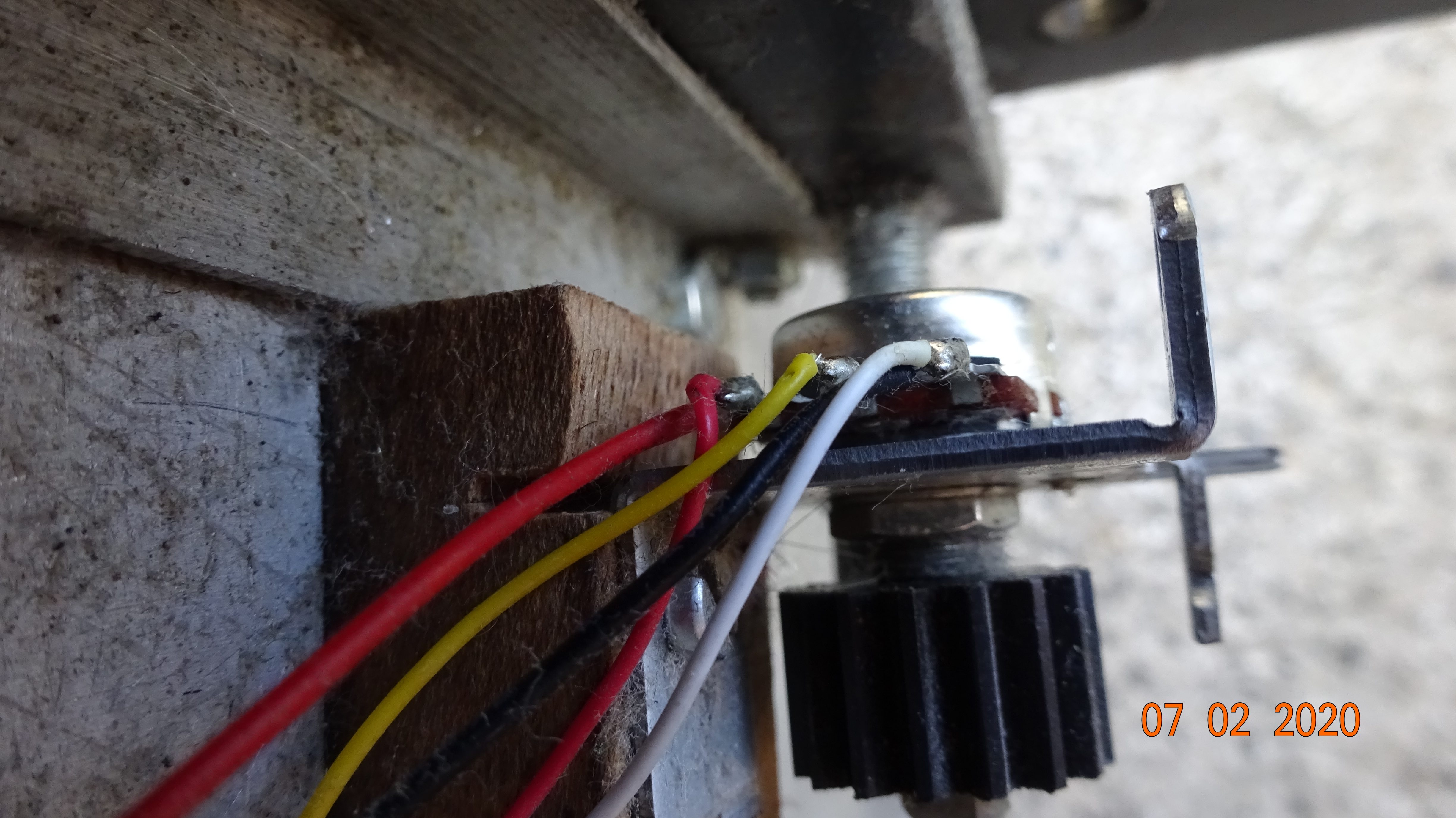
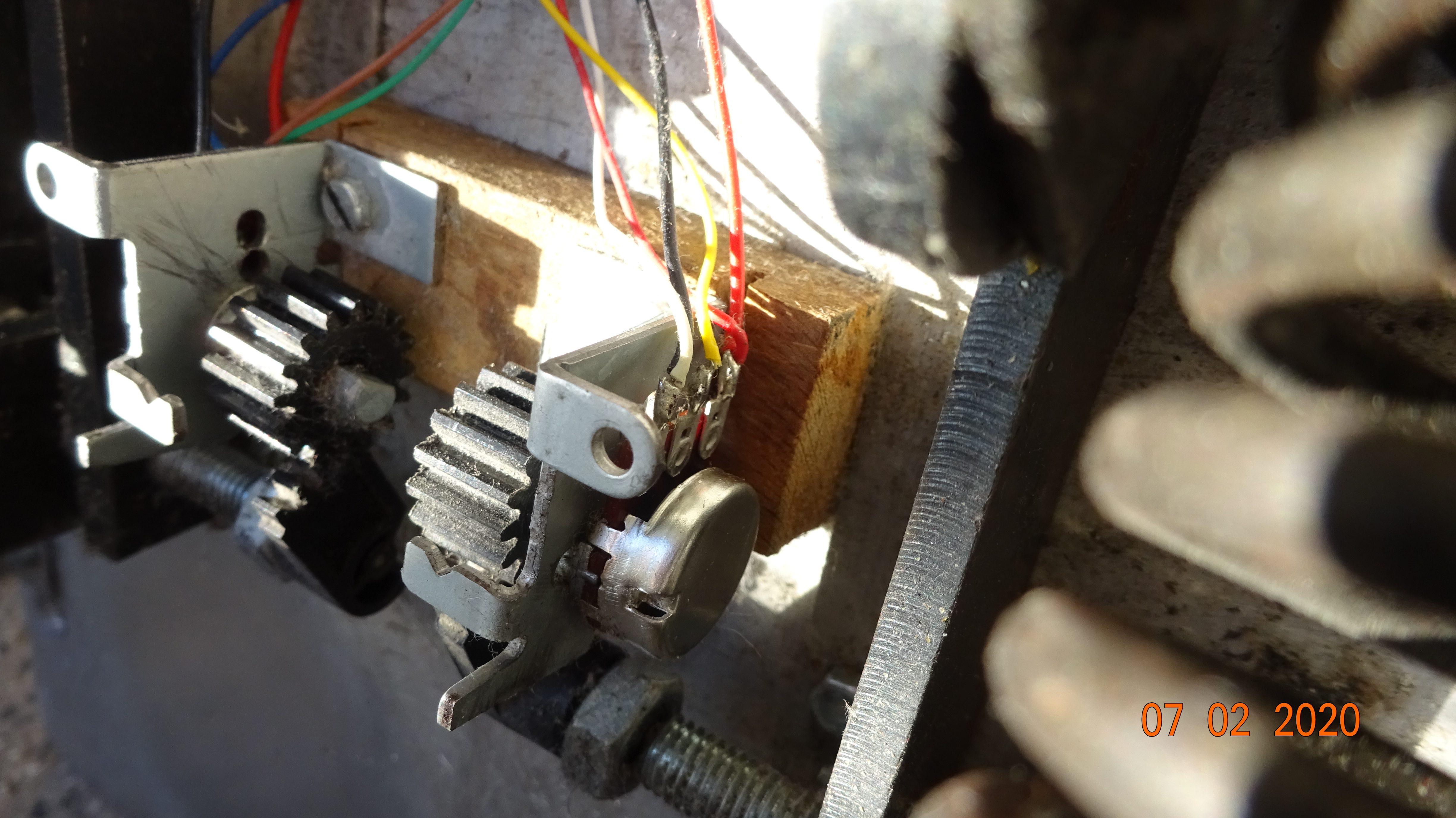
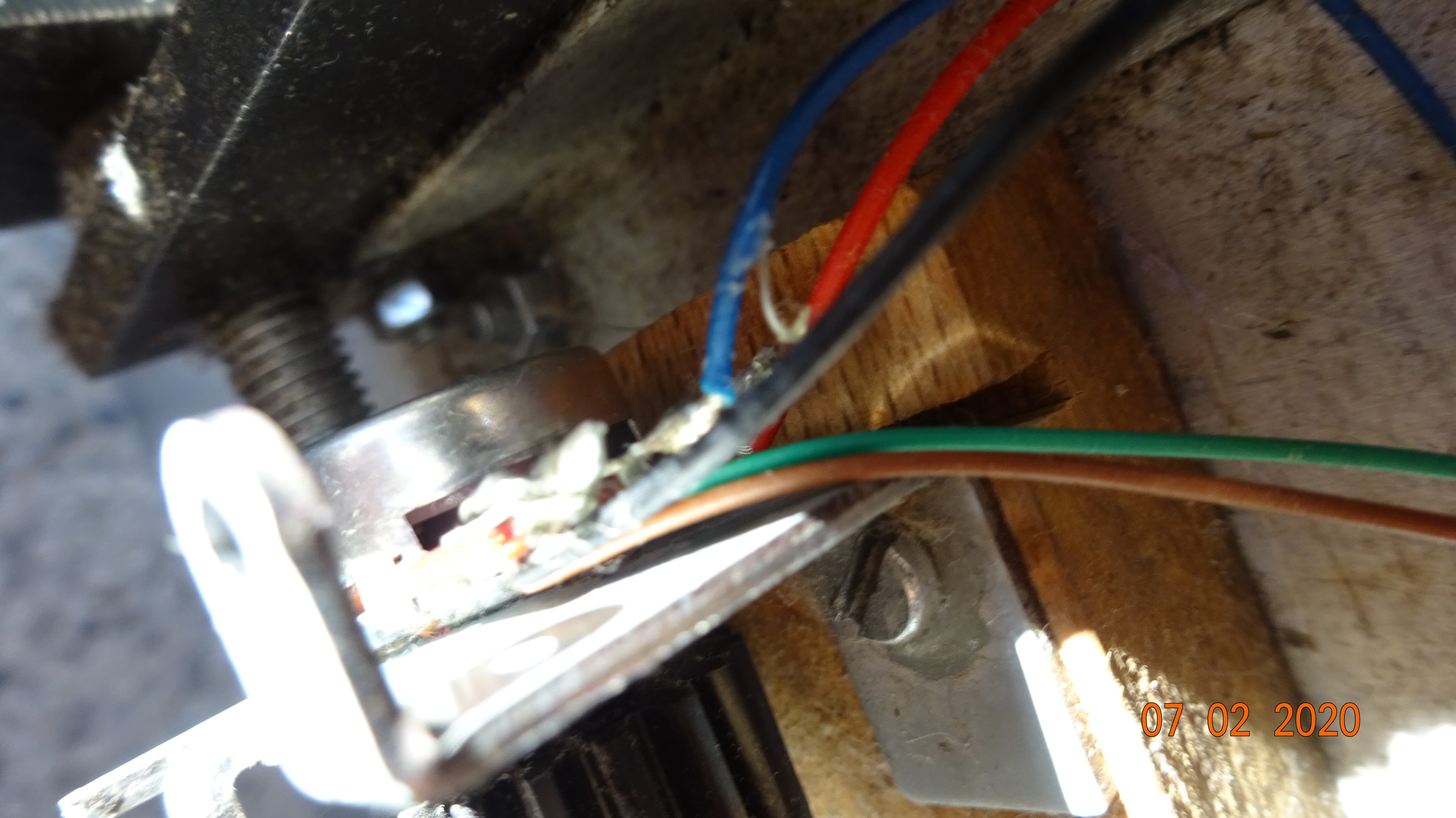
The two pedal set has the wiring for all three pedals,I recently decided to build my own pendulum pedal set from metal to utilise a hydraulic gadget I devised for a real brake feel,using the throttle pedal and bits from a t150 2 pedal set.Opening the pedals revealed a green wire soldered to the negative terminal on the brake pedal pot,( clutch signal pulled to earth,so that the wheel thinks its always up)so I decided to use the two plastic pedals for throttle and clutch and made a steel one to replicate them for the brake pedal,keeping the factory geometry between pedal and pot keeps it simple. I used a £2 generic 25K linear taper(B designation) 60 degree potentiometer from EBay for the clutch pedal and the cog came from a pile of old automotive throttle bodies I have lying around the workshop,using a bit of rough maths and being forced to use the cogs I had I managed to alter the gear on the clutch pedal pot so it has full movement but over a longer throw,as it does in reality.The wiring is simple just replicate the 2 pedal set up but connect green to the centre of the new pot and a jumper from live(red) and earth( brown or white) to the respective terminals on the new pot.I compared the ramps on both OE and generic pots, they are no different.
 
Hello, I have a thrustmaster tmx steering wheel, when I connect the pedals, the mode LED, lights up yellow and red, and starts giving random values only, what could be, greetings and thank you very much
 
Hello, I have a thrustmaster tmx steering wheel, when I connect the pedals, the mode LED, lights up yellow and red, and starts giving random values only, what could be, greetings and thank you very much
 
Back