Course Maker Toolbox

  • Thread starter eran0004
  • 104 comments
  • 34,529 views
You use the pen tool to add "polygon points" (vertices, basically). The straights are drawn between the points and curves are created automatically between the straights. The curve consists of a circular arc in between two transition curves. The transition curves are used to create smooth entries and exits, they also help to make the track easier to "read" for the driver. You can adjust the radius of the circular arc and the length of the the transition curves.

If you want to replicate a real track or a real road you can import a reference path with gpx data, to help you align the vertices.

The elevation data can be edited in the elevation editor, which is a separate application.
Take an example on interlagos from which I was able to import it. I tried to do point to point, that is to say turn by turn and unfortunately it doesn't work like that.
grttg.PNG
 

Attachments

  • saoo.PNG
    saoo.PNG
    25.9 KB · Views: 16
Last edited:
The points are too close to each other. The track is procedurally generated and generally one point per corner is enough. In special cases you can subdivide the corner into two or three parts if you want the radius to change.
 
The points are too close to each other. The track is procedurally generated and generally one point per corner is enough. In special cases you can subdivide the corner into two or three parts if you want the radius to change.
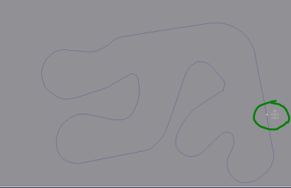
It is enough that I put less points to create my track?. If yes, it would make my corners inconsistent i.e. not similar to the real track?. Take an example of the Vias of portiragnes Kart track. I put this to mean the start finish line
 

Attachments

  • Kart Vias.zip
    2.1 KB · Views: 14
  • Vias.PNG
    Vias.PNG
    5.8 KB · Views: 13
Last edited:
It is enough that I put less points to create my track?. If yes, it would make my corners inconsistent i.e. not similar to the real track
You can put multiple curves after one another to create irregular curves, but there’s a limit in how small each curve segment can be. The minimum length is around 15 meters, if you go below that the track will not function properly in the game.

The original app is better suited for connecting multiple curves than my Python app. You can do it with the Python app too, but it’s a little tricky.
The problem with the app is that i can't put the start/finish line on a short straight for example like the Interlagos for example
 
Last edited:
The problem with the app is that i can't put the start/finish line on a short straight for example like the Interlagos for example
True.

The best advice I can give is to reduce the number of points as much as possible. Most curves you can probably approximate pretty well with 2-3 points. It won’t be perfect but it might be good enough.
 
Track Layout Creator

Latest version: 3.4 (2017-11-18)

Requirements
Python 3.6 or above
Windows (Linux/UNIX and Mac OS may work, but is untested)

About
The Track Layout Creator is a community-developed course maker. It's intended to be a quick and easy way to create advanced and precise track layouts and to achieve that it is using a polygon modelling method where straights are drawn between the polygon points while turns are generated by rounding the corners of the polygon. The tool samples the heightmap of the scene to generate the elevation data.

View attachment 675626

Basic commands
At the top left of the window there is a toolbar, with the following tools:

View attachment 636464 View attachment 636470 View attachment 636465 View attachment 636467View attachment 664670 View attachment 636468 View attachment 636473 View attachment 636474View attachment 636466View attachment 636475 View attachment 636471 View attachment 636472 View attachment 636469

View attachment 636464
Pan tool: Click and drag to pan the view. Panning can also be done with any tool by right-clicking on the canvas (not on a polygon point) and dragging.

View attachment 636470
Selection tool: Click on a polygon point to select it. Shift-click to add/remove from selection. Click elsewhere to clear selection. Click on a selected point and drag to move all the selected points. Press <a> to quickly select all points. Press <delete> to delete any selected points. Right-click on a polygon point and drag up / down to change the turn radius of that corner.

View attachment 636465
Pen tool: Click on the canvas to place a polygon point at the location. Click on a polygon line to insert a point between the two endpoints of the line. Shift-click on a polygon point to delete it.

View attachment 636467
Rotate tool: Click and drag to rotate the selected points.

View attachment 636468
Scale tool: Click and drag to scale the selected points (also scales the turn radius).

View attachment 664670
Camber tool: Click and drag to adjust the camber of the selected points. Setting camber to "Global" makes the application calculate the camber angle based on the global camber settings in the left window.

View attachment 636473 View attachment 636474
Mirror x / mirror y: Click to mirror the selected points around the x or y axis.

View attachment 636466
Reverse tool: Click to reverse the direction of the track.

View attachment 636475
Random tool: Click to apply a random translation of the selected points.

View attachment 636471 View attachment 636472
Zoom in / out: Click to zoom in / out. Zooming can also be done by scrolling the mouse wheel, or by pressing <+> or <->.

View attachment 636469
Camera tool: Click to export a postscript image file of the current view. PostScript files are vector graphics files and can be converted to other formats such as .jpg or .png here: http://psviewer.org/ConvertPsToJpg.aspx

Menu options
File menu
  • Load track (ctrl-o): Loads a saved track in the *.trk format. A *.trk file contains all the track settings, in addition to the polygon data.
  • Save track(ctrl-s): Saves the track as a *.trk file.
  • Import polygon: Imports a polygon file (.pgn). This contains only polygon data.
  • Export polygon: Exports the polygon as a .pgn file.
  • New in 3.4: Import reference path (.gpx): Imports a .gpx file and uses it as a reference path.
  • Import Reference path (.csv): Imports a .csv file containing Latitude and Longitude data, for use as reference path.
  • New in 3.1: Import reference path (.ted): Imports a .ted file and uses it as a reference path.
  • Export to TED: Exports the track as a .ted file, which can be uploaded to the GT6 game server.
  • Export to PostScript: Exports the current view as a PostScript file. See description of Camera tool above.
  • New in 3.3: Draw isometric view: Creates a new window where a snapshot of the current view is drawn in an isometric projection.
  • New in 3.2: Preferences: Various track and display options (most of them used to be in a panel to the left of the canvas).
  • Quit: Quit the application.
Edit menu
  • Undo (ctrl-z)
  • Redo (ctrl-y)
Display menu
  • Check items to display them, uncheck to hide.
Scenery menu
  • Select the location of your track (Eifel, Eifel Flat, Andalusia, Death Valley)

Euler curves and hairpins
Version 3.0 introduces Euler curves and procedural hairpins.
  • Euler curves adds spiral curves at the start and the end of a turn. This provides a linear increase in curvature until the main curvature of the turn (determined by the radius value of the polygon point) has been reached and makes turn entry and exit much smoother and creates a more natural flow of the road.
  • Procedural hairpins are automatically generated for all turns with an angle greater than 140 degrees and a radius less than 30 meters and greater than 10 meters.
  • New in 3.1: Selecting a polygon point now displays handles that will let you adjust the number of Euler segments / the length of the procedural hairpin for that corner. Just click on a handle and drag to adjust. Set it to 1 to turn an Euler curve into a normal curve.

Navigation panel
Version 3.2 introduces the navigation panel.
  • The navigation panel is the dark blue strip below the canvas.
  • The navigation panel displays a preview of the track's elevation. The preview is colour-coded to indicate how steep the slope is.
    • Black: 20% or greater
    • Red: 15-20%
    • Yellow: 10-15%
    • Light blue: 0-10%
  • Left-clicking on the navigation panel centers the canvas on the corresponding track location and places a cursor on that location.
  • Pressing <c> on the keyboard centers the canvas on the cursor.
    • If no cursor is placed, the canvas is centered on the average coordinate of the entire track.
  • Right-clicking on the navigation panel removes the cursor.

Limitations
  • Make sure that no segments (straights or curves) of the track have a length shorter than 15 meters. The game sometimes struggles with lengths shorter than 15 meters and can lead to AI failing to navigate a corner properly or an invalidated lap time. Keep in mind that all turns consist of at least two segments, so the length of a turn should not be less than 30 meters.
  • Placing a curve on a main straight with a pit wall can lead to unexpected behaviour, especially when the curve is placed at the pit entry or pit exit. This can lead to the pit collision mesh extending onto the road or to AI navigation issues in the pit. Eifel seems to be more sensitive to this than Andalusia and Death Valley, but issues can occur at all scenes. Update: When placing an Andalusia pit on a curve, make sure that: (1) The first 200 meters are straight; (2) That the pit exit is on a straight or in a right turn.

Warning indicators
There are two types of warnings that will be indicated on the screen:
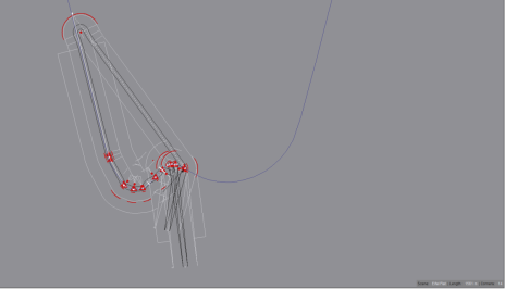
  1. Length of a road segments is less than 14 meters: Indicated with red lines next to the road + a red triangle on the road.
    This indicates that the distance between two CP points (which are used to construct the track) is too short, which can lead to AI navigation issues or lap invalidation in the game. Note that a turn is at least two segments, so the turn length should be at least around 30 meters.

  2. Turn radius is less than the road border width: Indicated with red lines next to the border + a red dot at the arc center.
    This indicates that the border around the road is intersecting with itself. There is no performance issue with this, but it may look ugly.
Examples: In the image below there are four warnings displayed. From left to right:
  1. This straight segment is too short.
  2. This curve is too short and the border is intersecting with itself.
  3. This curve is too short.
  4. The border of this curve is intersecting with itself.
View attachment 675703

3D View
View attachment 689529

Version 3.3 introduces a 3D view (File -> Draw isometric view). This creates a new window that allows you to look at the track in an isometric projection. In this view the elevation is scaled up by a factor of four, to give you a better idea of the shape of the terrain.
  • The 3D view only displays the part of the track and the landscape that is visible in the main window (it takes a snapshot of the landscape). You can pan and rotate the 3D view, but the piece of the landscape that is displayed is fixed. If you want to see another part of the landscape you have to go back to the main window, pan the view to that location and then open up another 3D view window.
  • Just like with the main canvas, you can export a screenshot of the 3D view to a postscript file by clicking on the camera icon in the the 3D view toolbar. The exported file can be found in the img folder and is named iso.png.
  • You can't make any edits to the track in the 3D view - it's for viewing only.
and how can i drive on this tracks, idk how to pass the track to the game
 
and how can i drive on this tracks, idk how to pass the track to the game
You need to ask someone who knows how to mod the game, I don’t know how it works. Back in 2017 we would upload the tracks to the server and then import them in the game from there, but now the servers are gone.
 
To expand on the reply above, the GT6 tool is specifically the Track Path Editor - it generates a path that the game's built-in track generator then uses to generate all of the visuals, road surfaces, and so on. Effectively all that the app outputs is a list of invisible checkpoints, it's not a track generator / maker in itself.
 
To expand on the reply above, the GT6 tool is specifically the Track Path Editor - it generates a path that the game's built-in track generator then uses to generate all of the visuals, road surfaces, and so on. Effectively all that the app outputs is a list of invisible checkpoints, it's not a track generator / maker in itself.
I wrote a script that can generate the road and the terrain in Blender from the heightmap and the .ted file instructions. The bank angle is a bit glitchy and needs some more work though (it gets inverted occasionally). You also need to connect the road to the terrain manually and add textures and props to the model, so it’s by no means a complete and finished 3D model.

Here’s an example of what it may look like when you’ve connected road with terrain and added some basic textures.


Guys another question the tracks can be in AMS 2 too?, and do you know how to model the 3d things like trees
If AMS 2 supports modding I see no reason why not. But as mentioned above you need to spend quite a lot of time and effort to create the 3D model. What you can expect to get from the course maker is basically a design tool to create a good layout.
 
Back